Virtual Assemblies: Measuring Clearance & Interference
Below are the beginning stages of a virtual assembly project. In this scenario, a prominent automotive shifter manufacturer was having issues with shifter buttons sticking or wobbling. Obviously on a safety critical part like this they needed to learn as much as possible about what could be causing this.
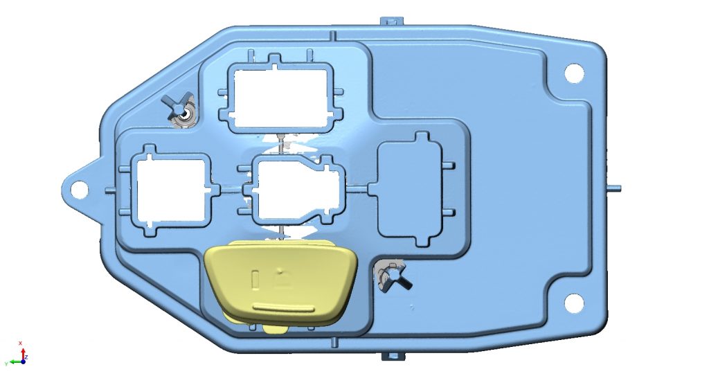
We started by scanning the Shifter Base. Then we scanned the individual buttons. You can see these two individual components below.
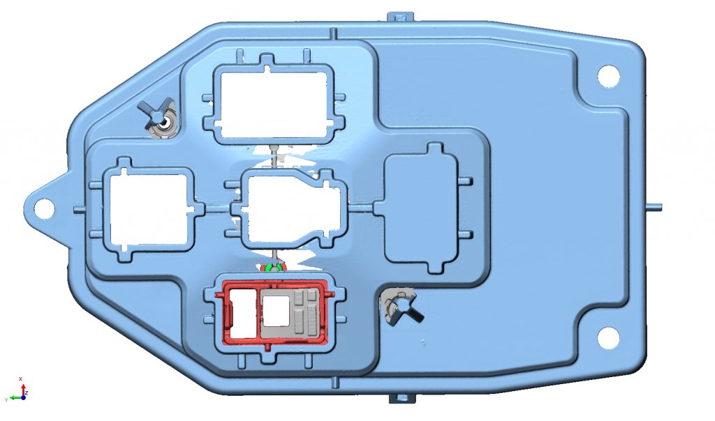
In order to align the buttons to the base properly we also needed to scan what is called the Plungers and fit them into the Plunger Slots of the Shifter Base. The plunger is in red below.
Here is a +X view through the center of the assembly showing all of the components including the rubber stoppers. These were also individually scanned and aligned to the Shifter Base.
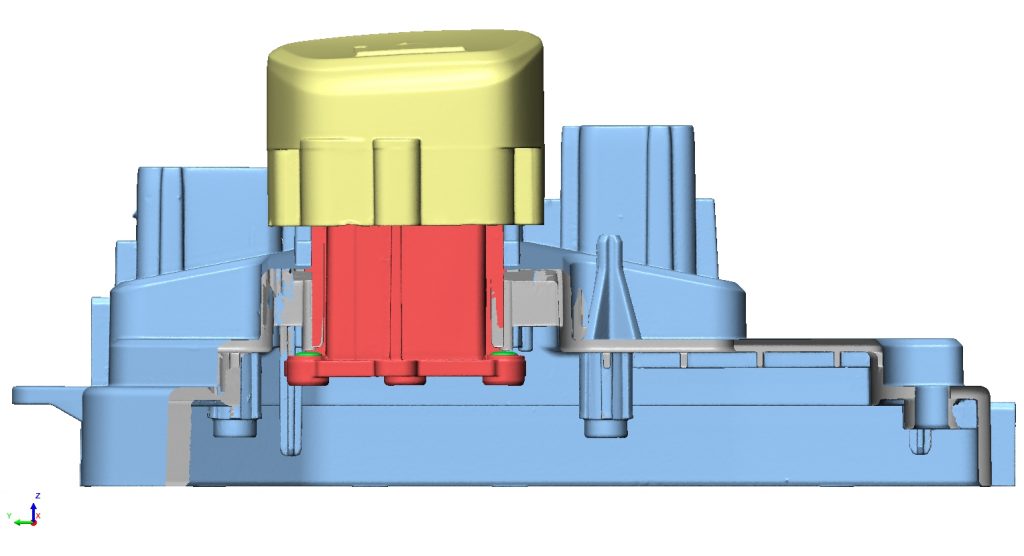
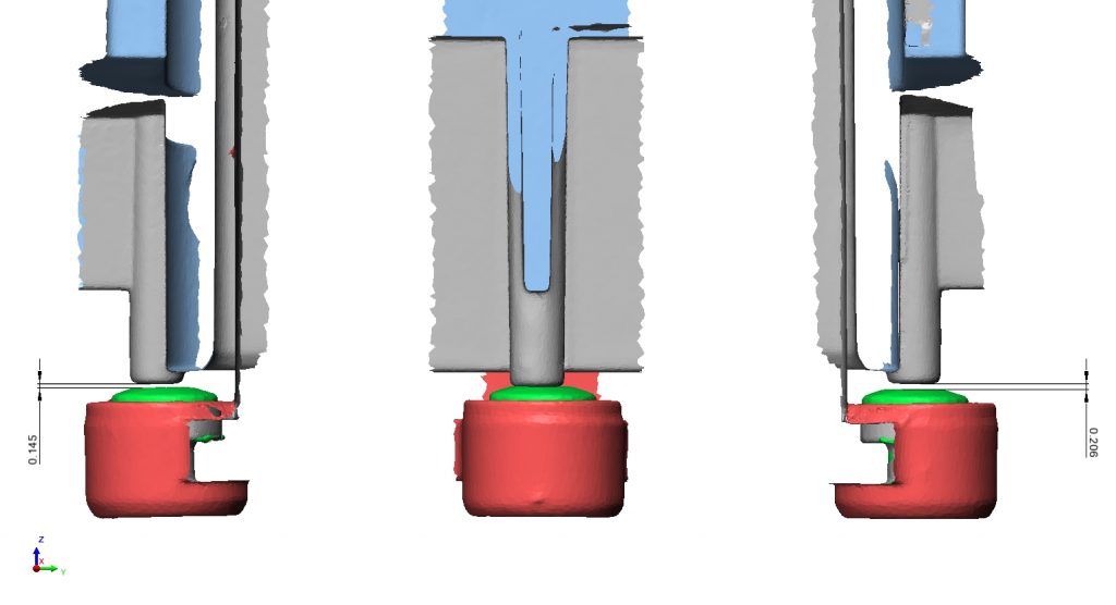
Immediately it was discovered that only one of three rubber stoppers was interacting with the button in its “UP” state. This is not critical to the function of the button but became useful for aesthetic purposes. It revealed the cause of a separate problem why the gaps between the buttons had a large variation.
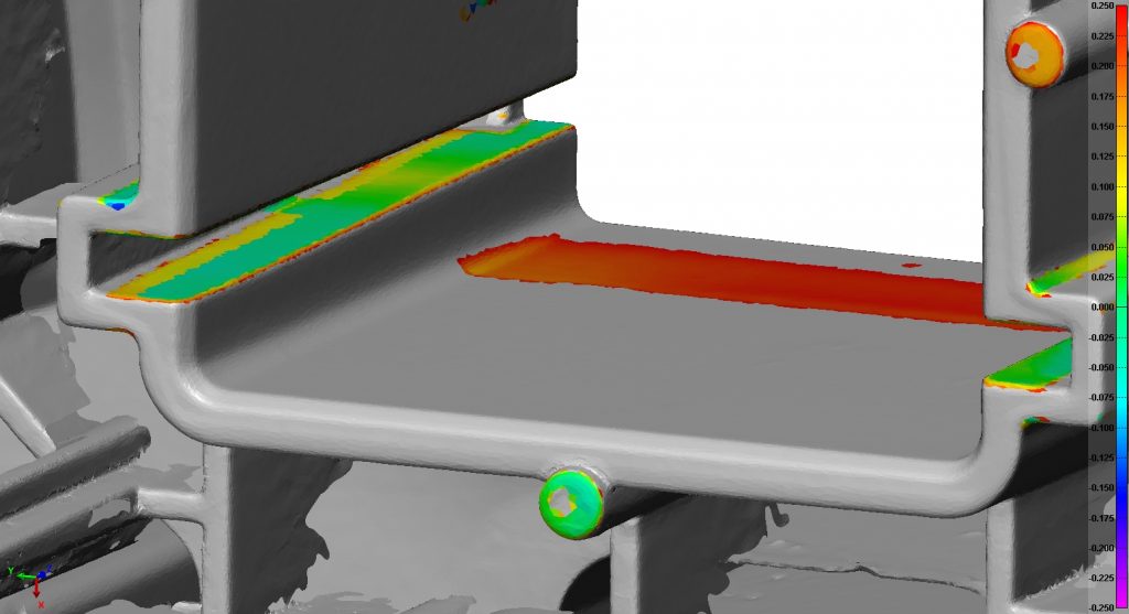
What we already know is that there are both areas of clearance (gaps) and interference (friction). This is known because at different positions along the plunger slot the buttons either wiggle or tighten up. But where exactly does this happen? Below is a “Heat Map” of the gap between the plunger slot and the plunger in the up position. This heat map was also measured separately at the middle and down positions. Colors between green and red show areas of clearance; green to blue show areas of interference. This means that both at the top and bottom of the slot there is plastic bowing inwards from the middle. From this we still do not know if this is caused by the plunger or the plunger slot.
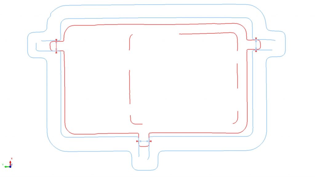
Below is what is termed a “Cross Section.” We can cut a slice through the project at any location, direction, or angle to see what is happening. From this we can measure the widths of both the slot and the plunger at the exact same height in order to compare how close to CAD’s perfect width they are, and to compare their widths to each other. Of course measuring standard widths is possible with many measuring devices. However, measuring their widths at exact locations, in an assembled state while taking into consideration both part form and those assembly constraints, is only possible using virtual assembly.
Other practical applications for virtual assembly include:
1. learning how much actual space is available inside of something and where those spaces are
2. learning where leaks may be (gaskets, non flat planes, and so on)
3. testing prototype parts before production


